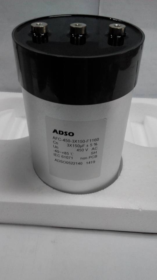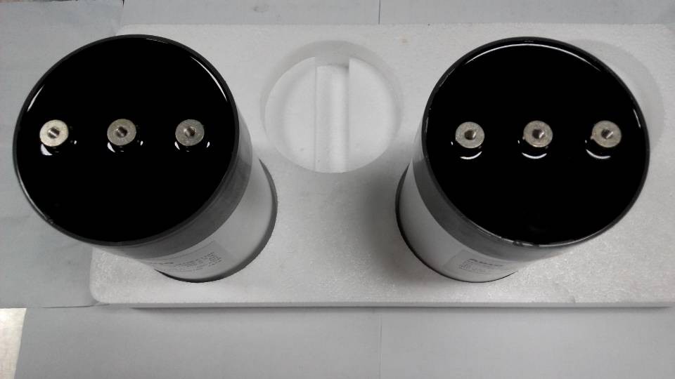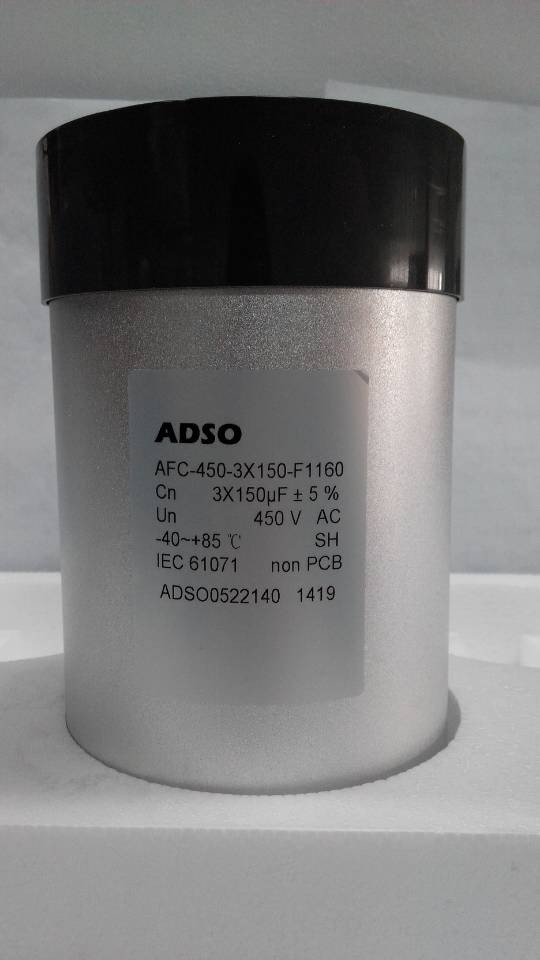
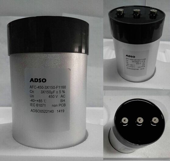
1、圓柱體螺孔引出,采用螺栓安裝,底部螺栓固定,方便簡潔;
2、電壓450VAC;容量3*100--3*200uf,集成三角形接法;
3、超低ESL、ESR,高頻特性好,電流大,環境適應性高;
4、用于輸出濾波,針對光伏逆變器網測LC專用設計;
Overview:
The AFC Series is a polypropylene metallized film with cylindrical aluminium can type filled with resin,
screw terminals and plastic deck.
Application:
AFC-450 is designed for solar inverter output AC filter; AFC-850 is designed for Wind power converters output AC filter.
Electrical data:
|
Reference standards |
IEC 61071 , IEC 60068 , UL 810,RoHS compliance |
|
Standard capacitance tolerance |
J: ±5% |
|
Dielectric dissipation factor (tan δ0) |
2 X 10⁻⁴ |
|
Min/ Maximum temperature Θmin/Θmax |
–40 °C/+ 70 °C |
|
Storage temperature Θstg |
–40 °C ... +85°C |
|
Maximum hotspot temperature Θhs |
+70 oC |
|
Climatic category |
40/70/56 |
|
Permissible Relative Humidity |
Annual average ≤ 70%; 85% on 30 days/year randomly distributed throughout the year. Dewing not admissible |
|
Maximum altitude |
3000 m above sea level(derating curves available upon request) |
|
Expected lifetime |
100 000 h at Urms @ Θhs 60°C |
|
Capacitance drop at end of life |
-5% (typical) |
|
Fit rate |
100 (100 000 h at Θhs 60°C) |
|
Test voltage between terminals |
UTT 1.5 Urms , 10s |
|
Test voltage between terminals and case |
UTC 3500 VAC, 10s |
|
Dissipation factor tan δ (100Hz) |
≤2.0X10⁻³ |
|
Self inductance (Ls) |
≤ 60 nH |
|
Insulation Resistance |
Ri x C ≥ 10,000s at 100 VDC/1min at +25°C |
|
Life test According to |
IEC 61071 |
|
Impregnation Resin filling |
Non PCB, dry type |
|
Protection |
Aluminium case with or without, threaded bolt M12 Plastic deck flame retardant execution UL 94 V–0 Thermosetting resin sealing UL 94 V–0 compliant |
|
Cooling |
Naturally air-cooled (or forced air cooling) |
|
Degree of protection |
Indoor mounting |
|
Installation |
Any position |
|
Max. torque (case) |
M12 stud 8 Nm |
|
Max. torque terminal |
Internal thread M6: 4 Nm |
|
Can material |
Aluminium, filled with resin |
|
Lid |
Plastic (UL94-V0) |
|
Terminals |
Internal thread M6 x10mm |
|
Imax (Terminals) |
100A |
|
Base mounting stud |
M12 |
|
K |
36 |
|
L |
20 |
|
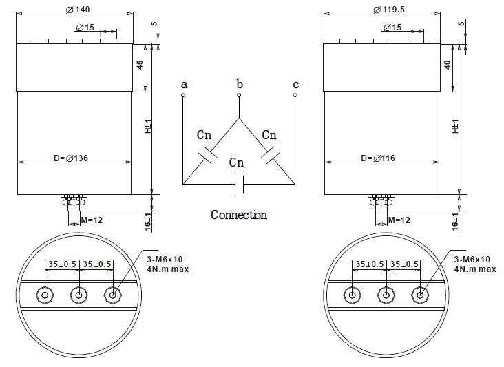
Connection |
Three-phase, delta connected |
AFC Series
Urms 450V Us 1400V UTT 675VAC/10s UTC 3500VAC/10s
|
Ordering code |
Cn (μF) |
Imax① (A) |
Ipk (KA) |
Is (KA) |
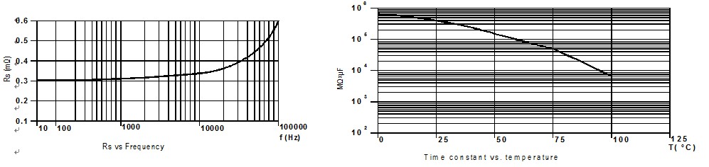
Rs (mΩ) |
Ls (nH) |
Rth (K/W) |
D (mm) |
H (mm) |
Weight (kg) |
|
AFC-450-3X100-F1160 |
3×100 |
3×50 |
2.1 |
6.3 |
3×1.1 |
50 |
1.7 |
116 |
185 |
3.50 |
|
AFC-450-3X120-F1160 |
3×120 |
3×55 |
2.5 |
7.6 |
3×1.0 |
50 |
1.7 |
116 |
185 |
3.44 |
|
AFC-450-3X135-F1160 |
3×135 |
3×60 |
2.8 |
8.5 |
3×0.9 |
50 |
1.7 |
116 |
185 |
3.40 |
|
AFC-450-3X150-F1160 |
3×150 |
3×65 |
3.2 |
9.5 |
3×0.8 |
50 |
1.7 |
116 |
185 |
3.36 |
|
AFC-450-3X180-F1360 |
3×180 |
3×70 |
3.8 |
11.3 |
3×0.8 |
50 |
1.4 |
136 |
185 |
4.70 |
|
AFC-450-3X200-F1360 |
3×200 |
3×75 |
4.2 |
12.6 |
3×0.7 |
50 |
1.4 |
136 |
185 |
4.64 |
①. Imax @ ΘA 40°C, that lead to a ΔT of ~ 60°C in the hotspot, Θhs =ΘA + ΔT.
Typical polypropylene dielectric characteristics
Rated capacitance CN
Capacitance value
rated at20°C/ 50 Hz.
Rated AC voltage UN
Maximum operating peak recurrent voltage of either polarity
of a reversing type waveform for which the capacitor has
been designed.
Rated DC voltage UNDC
Maximum operating peak voltage of either polarity but of a
non-reversing type waveform,for which the capacitor has
been designed,for continuous operation.
Ripple voltage Ur
Maximum value of the peak-to-peak alternating component of the unidirectional voltage. This value is stated only for DC-capacitors. The peak-to-peak value of AC- and AC/DC-types is always 2 × UNAC.
Non-recurrent surge voltage Us
Peak voltage induced by a switching or any other disturbance of the system which is allowed for a limited number of times and duration.
- Maximum duration: 50 ms / pulse. Maximum number of occurrences: 1000 (during load).
Insulation voltage Ui
Rms rated value of the insulation voltage of capacitive elements and terminals to case or earth.
rms voltage Urms
Root mean square of max. permissible value of sinusoidal
AC voltage in continuous operation. In power electronics,
the RMS voltage is usually not the rated voltage value of
the capacitor.
Maximum current Imax
Maximum rms current for continuous operation.
Maximum rate of voltage rise (du/dt)max
Maximum permissible repetitive rate of voltage rise of the operational voltage.
Maximum peak current ?
Maximum permissible repetitive current amplitude during continuous operation.
Maximum peak current (?) and maximum rate of voltage rise (du/dt)max on a capacitor are related as follows:
? = C × (du/dt)max
Maximum non-repetitive rate of voltage rise (du/dt)s
Peak rate of voltage rise that may occur non-repetitively and briefly in the event of a fault.
Maximum surge current ? s
Admissible peak current induced by a switching or any other disturbance of the system which is allowed for a limited number of times (1000 times) and duration (50 ms / pulse).
?s = C × (du/dt)s
Ambient temperatureΘA
Temperature of the surrounding air, measured at10 cmdistance and 2/3 of the case height of the capacitor.
Lowest operating temperatureΘmin
Lowest permitted ambient temperature at which a capacitor may be energized.
Maximum operating temperatureΘmax
Highest permitted capacitor temperature during operation, i.e. temperature at the hottest point of the case. It is, however, not sufficient to monitor the surface temperature. Life-span and safe operation crucially depend on the observance of the hotspot temperature.
General Remarks
Hot-spot temperatureΘhs
Temperature zone inside of the capacitor at hottest spot. It has to be noted that,depending on the thermal power dissipation generated inside the capacitor,there is always a temperature difference between hotspot and surface. As the hotspot is usually not accessible for measurement, Θhs must be calculated based on the data stated in the catalogue or data sheet:
Θhs =ΘA + Irms2x ESR x Rth
Important: No thermal dissipation losses are admissible when operating a capacitor at an ambient temperature equal to the upper category temperature,i.e. Irms and Q shall be zero (operation at pure DC voltage) !
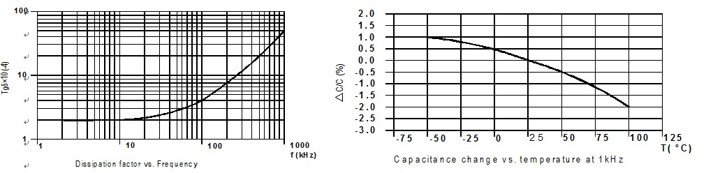
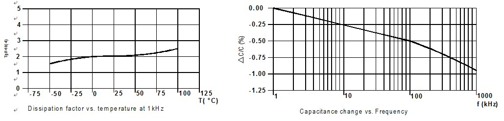
Dielectric dissipation factor tanδ0
Constant dissipation factor of the dielectric material for all capacitors at their rated frequency.The typical loss factor of pp film is tanδ0 = 2 x 10⁻⁴.
Dissipation factor tanδ
Loss factor of the capacitor at sinusoidal ac voltage and applied frequency.It is calculated as follows:
tanδ (?) = tanδ0 + Rs x 2π? x CN
Series resistance Rs
The sum of all ohmic resistances occurring inside the capacitor.
Equivalent Series Resistance ESR
Represents the sum of all loss resistances occurring in the capacitor. It depends on frequency and is essential for the calculation of the capacitor’s total power losses.
ESR = Rs +tanδ0 /(2π? x CN)
Thermal resistance Rth
The thermal resistance indicates by how many degrees the capacitor temperature at the hot spot rises in relation to the dissipation losses.
Maximum power loss Pmax
Maximum permissible power dissipation for the capacitor’s operation.
Pmax =(Θhs –ΘA)/Rth
Self inductance Ls
The sum of all inductive elements which are contained in a capacitor.
Resonance frequency Fr
The lowest frequency at which the impedance of the capacitor becomes minimum.
Fr = 1/(2π ?Ls x CN )
Rated energy contents WN
Energy stored in the capacitor when charged at rated voltage.
WN =1/2CN× UN2
Clearance in air L
The shortest distance between conducting parts of the terminals or between terminals and case. In this catalogue, we state only the shorter.
Creepage distance K
The shortest distance along an insulated surface between conducting parts of the terminals or between terminals and case. In this catalogue, again we state only the shorter.
AC capacitor Lifetime statements vs. Failure rate
In the lifetime expectancy graphic, statements for more than 200,000 hrs are cut off as they are technically unreasonable. For higher hotspot temperatures, no statements are made regarding operation at overvoltage: the simultaneous operation at limit values results in unpredictable conditions. Here, the statement of a FIT rate - that reflects the growing risk at such extreme conditions - would be of far better use.
AC capacitor Lifetime Expectancy Graphs
AC capacitor FIT rates (Failures In Time):
By reflecting the probability (in other words: risk) of failures during the operating period under selected operating conditions, it provides information on what effects to expect when de-rating (or over-loading) a capacitor. The failure probability of a component is a statistical value which is described by a log-normal distribution:
N = No × eˉλt
N = number of functional components after period t
No = total number of components at time t = 0
λ = failure rate
λ is the failure rate, which alternatively is also stated as the so-called FIT-rate (FIT = Failures In Time = λ×109). Service cycles may be calculated based on the so-called MTBF value (mean time between failures): MTBF = 1/λ. The failure rate is very closely linked with the operating temperature and the operating voltage applied to the capacitor. As standard, our FIT rates are related to a realistic (from a technical and statistical point of view) operating interval of t=100,000 hours, assuming a capacitor hotspot temperature of60°C. Hotspot is the only reliable criterion in relation to the capacitor’s temperature stress. The outside temperatures may be comparably low, however with high electrical stress the temperature rise in the capacitor may be substantial due to the power dissipation losses produced inside. This could result in the same temperature stress as a generally high ambient temperature.
The simultaneous operation of capacitors at highest permissible voltage and operating temperature should be avoided; otherwise, failure rates may increase beyond reasonable technical reliability.
In fact, a FIT rate of 50 would mean, for example: “If 10,000 capacitors are operated simultaneously for 100,000 hours at rated voltage and with a hotspot temperature of no more than60°C, then out of this batch no more than 100 pcs may fail during the entire period.” Any period during which the hotspot temperature is lower than60°C, or the voltage is less than rated voltage, will contribute to a reduction of the 100 FIT.
After the reference interval, the capacitors will continue operating; however the probability of failures may change. It shall be noted that the statements on FIT rates are based mainly on long-year empirical experience; at ADSO, we are conducting numerous and regular reliability tests to verify and back up our empirical knowledge. However dedicated studies designed to prove FIT rates would require the test of thousands of capacitors, over hundreds of thousands of hours, which is technically and commercially impossible. Even the use of statistical methods and accelerated ageing factors encounters physical and chemical limits.
Hence lifetime formulas such as
Lifetime (U) = LN x (Urated/Uworking)8 and Lifetime (Θ) = LN x 2(Θrated-Θworking)/7
should not be used to calculate absolute figures of expected lifetime. These rules and formulas are mainly designed to give an approximate feeling for the importance of voltage and temperature.
All standard items of ADSO are designed and dimensioned to comply with their FIT rate as stated in the catalogue or special data sheet. FIT rate statements related to longer reference intervals can be made on request. Further, capacitor designs can be adapted on request to achieve lower FIT at the intended operating conditions.
Based on our current state of knowledge derived from test data and experience, we quote the following FIT rates for our standard products at the a.m. conditions:
AC capacitor FIT rates Quota Graphs